
How would I bench test....
How would I bench test....
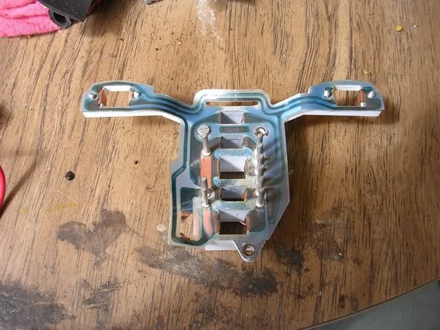
..the circuit in a bulb holder/instrument circuit board? This is a picture from Melville.
Cheers, Steve
Victoria, S.E.Oz.
1982 R100RSR100RS supergallery. https://boxerboy81.smugmug.com/R100RS
2006 K1200R.
1994 R1100GS.
Victoria, S.E.Oz.
1982 R100RSR100RS supergallery. https://boxerboy81.smugmug.com/R100RS
2006 K1200R.
1994 R1100GS.
Re: How would I bench test....
Two wires with appropriately sized alligator clips, larger for the battery and smaller for the circuit board terminals.
Study the circuits and you'll see where the grounds and the positives are.
Connect to a 12 volt battery and test away.
Study the circuits and you'll see where the grounds and the positives are.
Connect to a 12 volt battery and test away.
Lord of the Bings
Re: How would I bench test....
Thanks Jeff.ME 109 wrote:Two wires with appropriately sized alligator clips, larger for the battery and smaller for the circuit board terminals.
Study the circuits and you'll see where the grounds and the positives are.
Connect to a 12 volt battery and test away.
So leave the ground connected to neg on the battery and move the other from different terminals to the battery positive, watching for the lights to come on. Sounds easy enough. I wasn't sure if the circuit board might need further care. Cheers.
Cheers, Steve
Victoria, S.E.Oz.
1982 R100RSR100RS supergallery. https://boxerboy81.smugmug.com/R100RS
2006 K1200R.
1994 R1100GS.
Victoria, S.E.Oz.
1982 R100RSR100RS supergallery. https://boxerboy81.smugmug.com/R100RS
2006 K1200R.
1994 R1100GS.
Re: How would I bench test....
It's a bummer that these are no longer available for the earlier bikes, I use silver foil where the bulbs push in, it seems to help to make reasonable contact.
Charles

Replica 1070 R90/S (based on 82 RT)
1975 R90/6

Replica 1070 R90/S (based on 82 RT)
1975 R90/6
Re: How would I bench test....
I have a pre 1980 one that I need to test. It was from a 60/7 but fits many others. It might be kaput?chasbmw wrote:It's a bummer that these are no longer available for the earlier bikes, I use silver foil where the bulbs push in, it seems to help to make reasonable contact.
Cheers, Steve
Victoria, S.E.Oz.
1982 R100RSR100RS supergallery. https://boxerboy81.smugmug.com/R100RS
2006 K1200R.
1994 R1100GS.
Victoria, S.E.Oz.
1982 R100RSR100RS supergallery. https://boxerboy81.smugmug.com/R100RS
2006 K1200R.
1994 R1100GS.
Re: How would I bench test....
Steve remember that the position of the warninglights varies from model to model, eg your bike won't have a hydraulic fluid level light and the pre 1980 one will, my 75 has the indicator light at the bottom, my 82 has it at the top etc etc.
I have a feeling that the position of the oil warning light might have changed over the years?
I have a feeling that the position of the oil warning light might have changed over the years?
Charles
Replica 1070 R90/S (based on 82 RT)
1975 R90/6
Replica 1070 R90/S (based on 82 RT)
1975 R90/6
Re: How would I bench test....
Yep, that's why I want to be able to bench test a couple I have as they're pre 1980 and won't match the 1981 instrument board I have.
Btw, tonight I finally hacked the Wurth plug and 8 inches of the loom and spliced a good one into it, so now I have all idiot lights working. I've been without neutral and high beam for over a year, and the night lights haven't worked either. All's good now.
Btw, tonight I finally hacked the Wurth plug and 8 inches of the loom and spliced a good one into it, so now I have all idiot lights working. I've been without neutral and high beam for over a year, and the night lights haven't worked either. All's good now.
Cheers, Steve
Victoria, S.E.Oz.
1982 R100RSR100RS supergallery. https://boxerboy81.smugmug.com/R100RS
2006 K1200R.
1994 R1100GS.
Victoria, S.E.Oz.
1982 R100RSR100RS supergallery. https://boxerboy81.smugmug.com/R100RS
2006 K1200R.
1994 R1100GS.
Re: How would I bench test....
my first BMW R90/6 had a water damaged printed circuit
so as the pod has room I got a solid coated wire and did a hard wire traceing the original circuitit was a improvement and worked
so as the pod has room I got a solid coated wire and did a hard wire traceing the original circuitit was a improvement and worked
-
Ken in Oklahoma

- Posts: 3182
- Joined: Tue Aug 03, 2010 5:10 pm
Not exactly on topic.
A couple years ago the printed circuit wiring in my R75/6 instrument housing was giving me fits. After hours of looking for the problem I finally figured out that in about three places the electrical continuity of the connector pins with the printed circuit etch was intermittent. Though the connection looked OK (i.e. not corroded) it wasn't.
Then came the question, how could I do a repair? Ultimately I peeled back a piece of the protective plastic film at the base of the pin. To do the repair I used a strand of copper wire and soldered it to the etch. Then I took the loose end of the wire and made a wrap around the base of the pin, and soldered that.
I don't recall now quite how I did it, but I then painted the "injured" coating with something, perhaps a layer of epoxy glue.
FWIW
Ken
____________________________________
There's no such thing as too many airheads
There's no such thing as too many airheads
Re: Not exactly on topic.
Ken, you should realise that you're amongst friends, and that it is ok to say nail polish.Ken in Oklahoma wrote:
I don't recall now quite how I did it, but I then painted the "injured" coating with something, perhaps a layer of epoxy glue.
FWIW
Ken
Duane uses it all the time!
Lord of the Bings