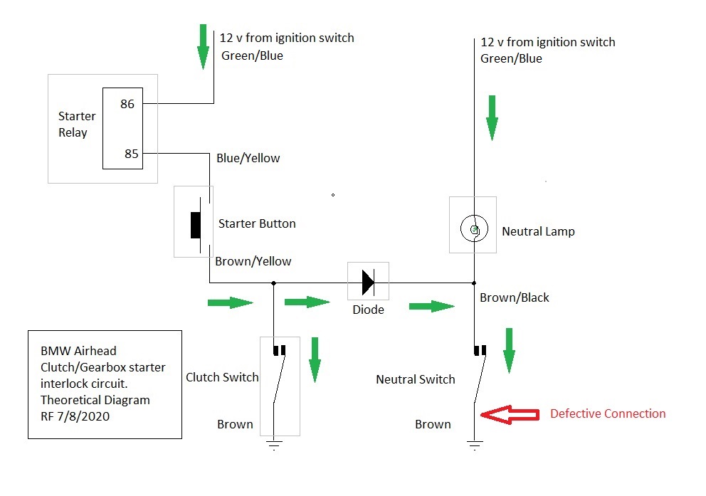
The starter relay (not the solenoid, the relay that is under the tank) takes it's current from the ignition switch via the kill switch. The positive side of the relay will always be at battery voltage when the ignition and kill switches are both on. Control of the relay is by the ground line. The ground side of the relay is connected to the starter button... if the starter button were connected direct to ground, the starter would work every time the button is pressed, even if the bike was in gear and the clutch wasn't pulled. This isn't 'healthy' because - a) engaging the starter against the resistance of a bike in gear isn't going to do the starter any favours and b) because it may result in the engine starting and the bike taking off when the rider isn't ready for it. BMW, therefore incorporated a system which prevents the starter from running unless a) - the bike is out of gear or b) the clutch is pulled. This is done as follows.
The ground side of the starter button is not connected direct to ground. It goes to a diode attached to the rear of the connection board in the headlamp shell. A diode is like a one way valve for electricity... current will flow through it one way but not the other. It then goes on to the clutch switch which is a 'pull to make' switch, that is to say that it carries current only when the clutch lever is pulled. With the clutch pulled, current can flow through the relay, the starter button and the clutch switch to ground which will
activate the starter.
The other end of the diode is connected to the neutral light switch which carries current to ground only when the gearbox is in neutral. When the gearbox is in neutral, current can flow through the relay, the starter button, the diode and the neutral switch to activate the starter.
The result of this circuit is that the starter can only engage when the gearbox is in neutral or when the clutch is pulled (or both of course).
The purpose of the diode is simply to stop the neutral indicator lamp lighting when the clutch is pulled.
Your symptoms imply that the connections as far as the diode in the headlamp shell are correct, that the diode is working and that connections to the neutral switch are OK (otherwise the bike wouldn't start in neutral). The assumption must be that the fault is in the circuit from the diode to groiund via the clutch switch.
I think you are saying that there is no voltage at the switch when the gearbox is in neutral. but that there is all of the time when the a gear is engaged. This suggests that the connection from the diode to the clutch switch is OK as there would be no voltage at all at that point if this connection were broken. That leaves the clutch switch itself and the wire from the clutch switch to ground. Since you say that you have replaced the clutch switch, the assumption has to be that the wire from the clutch switch to ground isn't connecting.
In short, therefore, you need to check the continuity of the Brown wire (with no tracer) from the clutch switch to ground.
At this point, my memory conflicts with the published wiring diagrams. The diagrams suggest that the wire goes direct to the main vehicle ground which is attached to the left coil mounting under the tank. My memory suggests that it actually goes to the ground connection in the headlamp shell. I may be wrong. In any case, I strongly believe that you will find the fault in that connection.
I attach a simplified wiring diagram of the starter circuit with the point that I expect to be at fault marked in red.

- Clutch Interlock(1).jpg (77.74 KiB) Viewed 1928 times
I don't know how familiar you are with electric control circuits so I have given as much information as I can. This has led to a long and detailed post and, If I am telling you things you already know, I apologise in advance
Rob
NB for others reading this post, the circuit discribed does not apply to all airheads. In particular, the /5 series circuit is very different. Other model years may have detail differences.
R