My H4 blew a few days back.
I installed a replacement. It's a pita job that one.
The next day after going over some corrugations on a dirt road, the headlight glass and chrome bezel popped right off.
So back in I go.
Hang the chrome at 12 o'clock over the headlight shell, press the bezel at 6 o'clock into position and tighten the screw.
Simple in'it No it's not It's a pita to do it I already tilt it up for better access to the screw. A longer screwdriver helps too.
Is there a trick I need to know about?
Installing an airhead headlight.
Cheers, Steve
Victoria, S.E.Oz.
1982 R100RSR100RS supergallery. https://boxerboy81.smugmug.com/R100RS
2006 K1200R.
1994 R1100GS.
Victoria, S.E.Oz.
1982 R100RSR100RS supergallery. https://boxerboy81.smugmug.com/R100RS
2006 K1200R.
1994 R1100GS.
Re: Installing an airhead headlight.
Like you said Steve, tilt the headlight up as far as you can to better align the screw.
Also as you said, clip on at 12:00 and push in at 6:00.
I use a short, small phillips to clear the fairing.
Also as you said, clip on at 12:00 and push in at 6:00.
I use a short, small phillips to clear the fairing.
Lord of the Bings
Re: Installing an airhead headlight.
Sounds too easy but it's always a bugger to seat it at 6 o'clock. It takes a firm grip to hold it in position whilst tightening the screw.
Seems it should be easier.
Cheers, Steve
Victoria, S.E.Oz.
1982 R100RSR100RS supergallery. https://boxerboy81.smugmug.com/R100RS
2006 K1200R.
1994 R1100GS.
Victoria, S.E.Oz.
1982 R100RSR100RS supergallery. https://boxerboy81.smugmug.com/R100RS
2006 K1200R.
1994 R1100GS.
-
- Posts: 1214
- Joined: Thu Aug 26, 2010 2:11 pm
- Location: Scotland UK, 20 miles from civilisation up a dead end road!
- Contact:
Re: Installing an airhead headlight.
The problem is propbably the layour of the wires inside the shell... well, no, the problem is really the whole idea of cramming the all of the electrics into the shell in the first place... seemed like a very good idea at the time but it can, as you say, be a real PITA.SteveD wrote: ↑Thu Aug 08, 2019 6:12 am My H4 blew a few days back.
I installed a replacement. It's a pita job that one.
The next day after going over some corrugations on a dirt road, the headlight glass and chrome bezel popped right off.
So back in I go.
Hang the chrome at 12 o'clock over the headlight shell, press the bezel at 6 o'clock into position and tighten the screw.
Simple in'it No it's not It's a pita to do it I already tilt it up for better access to the screw. A longer screwdriver helps too.
Is there a trick I need to know about?
The trick is to ensure that the wires inside the shell are routed leaving room for the headlamp bulb connector. Pictures from BMW literature show the wires neatly arranged around the outside of the shell. Sounds simple but I would be the first to acknowledge that it's by no means easy. This is one of the reasons why I've now relocated my fuses outside of the shell... wouldn't help with a headlamp bulb though.
FWIW, earlier models didn't have a screw at all, the headlamp just clipped into position with a spring clip at the bottom. With this type, you don't have a choice... if the wiring is exerting too much pressure on the headlamp, it just pops off. Quite embarassing to have the headlamp dangling by it's wires on the mudguard (if you're lucky) at 60mph...
Rob
Last edited by Rob Frankham on Fri Aug 09, 2019 8:35 am, edited 1 time in total.
Re: Installing an airhead headlight.
It's sure crowded in there but I always had difficulty despite a reasonably neat and tidy wiring setup. I have made it a little tighter in there with an Eastern Beaver loom too, but it's pretty much the same pita task.
Cheers, Steve
Victoria, S.E.Oz.
1982 R100RSR100RS supergallery. https://boxerboy81.smugmug.com/R100RS
2006 K1200R.
1994 R1100GS.
Victoria, S.E.Oz.
1982 R100RSR100RS supergallery. https://boxerboy81.smugmug.com/R100RS
2006 K1200R.
1994 R1100GS.
-
- Posts: 1214
- Joined: Thu Aug 26, 2010 2:11 pm
- Location: Scotland UK, 20 miles from civilisation up a dead end road!
- Contact:
Re: Installing an airhead headlight.
Totally agree... that's why I took the decision to take the fuses out of the shell... doesn't really change the problem just reduces the number of times you have to address it... and reduces the chance of having to do it at 02:00 in the pouring rain on the hard shoulder of a motorway. It also gave me the opportunity to add four extra fuses for accessories and reduce the number of wires around the forks that need to be routed carefully to avoid restricting the lock.
Rob
Rob
Re: Installing an airhead headlight.
I've previously done that Rob, different bike back in the '90's. I think Airbear, aka Charlie, has done it on his /6 too.
My speedo/tach glow lights (not the oil/gen/N/hb lights) have disappeared along with the tail light so I'm suspecting something amiss in there. I blew the headlight Friday 2/8, noticed the other lights 5/8 as we had a start up at dawn and it was obvious.
I'll get the wiring diagram out in a day or two....
Cheers, Steve
Victoria, S.E.Oz.
1982 R100RSR100RS supergallery. https://boxerboy81.smugmug.com/R100RS
2006 K1200R.
1994 R1100GS.
Victoria, S.E.Oz.
1982 R100RSR100RS supergallery. https://boxerboy81.smugmug.com/R100RS
2006 K1200R.
1994 R1100GS.
Re: Installing an airhead headlight.
Rob, where are your fuses located? Under the seat? Very interested.
1971 R50/5, 1980 R100T,
CRF 300 Rally, CRF 250F,
1947 James ML
CRF 300 Rally, CRF 250F,
1947 James ML
Re: Installing an airhead headlight.
I'm interested in how you relocated your fuses Rob. Are they now under the seat? In a fuse box? Sounds like a great idea.Rob Frankham wrote: ↑Fri Aug 09, 2019 4:59 amThe problem is propbably the layour of the wires inside the shell... well, no, the problem is really the whole idea of cramming the all of the electrics into the shell in the first place... seemed like a very good idea at the time but it can, as you say, be a real PITA.SteveD wrote: ↑Thu Aug 08, 2019 6:12 am My H4 blew a few days back.
I installed a replacement. It's a pita job that one.
The next day after going over some corrugations on a dirt road, the headlight glass and chrome bezel popped right off.
So back in I go.
Hang the chrome at 12 o'clock over the headlight shell, press the bezel at 6 o'clock into position and tighten the screw.
Simple in'it No it's not It's a pita to do it I already tilt it up for better access to the screw. A longer screwdriver helps too.
Is there a trick I need to know about?
The trick is to ensure that the wires inside the shell are routed leaving room for the headlamp bulb connector. Pictures from BMW literature show the wires neatly arranged around the outside of the shell. Sounds simple but I would be the first to acknowledge that it's by no means easy. This is one of the reasons why I've now relocated my fuses outside of the shell... wouldn't help with a headlamp bulb though.
FWIW, earlier models didn't have a screw at all, the headlamp just clipped into position with a spring clip at the bottom. With this type, you don't have a choice... if the wiring is exerting too much pressure on the headlamp, it just pops off. Quite embarassing to have the headlamp dangling by it's wires on the mudguard (if you're lucky) at 60mph...
Rob
1971 R50/5, 1980 R100T,
CRF 300 Rally, CRF 250F,
1947 James ML
CRF 300 Rally, CRF 250F,
1947 James ML
-
- Posts: 1214
- Joined: Thu Aug 26, 2010 2:11 pm
- Location: Scotland UK, 20 miles from civilisation up a dead end road!
- Contact:
Re: Installing an airhead headlight.
OK, the reasoning behind the move was:
Next was some flexible corrugated plastic conduit which I ran from a point under the tank to the new fusebox. This I secured to the fairing support for neatness.
Wiring was as follows:
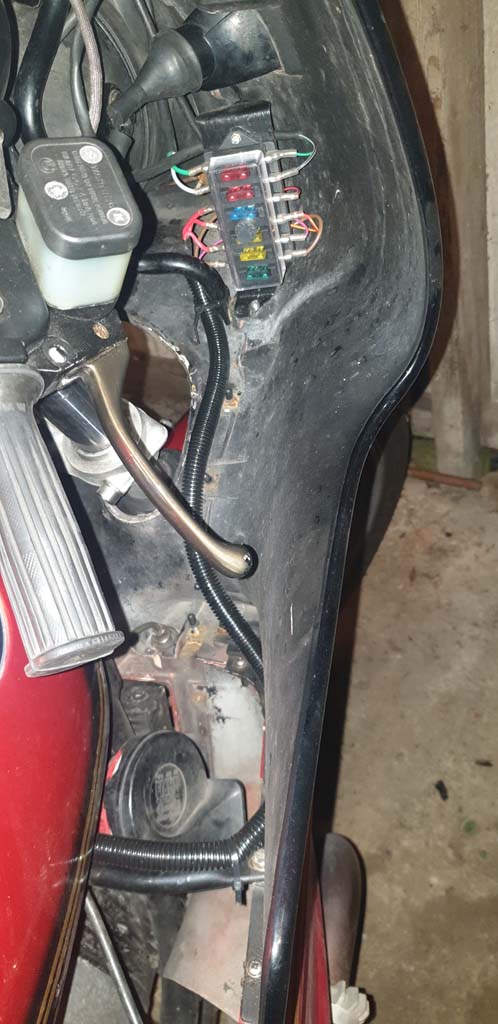
Fuse 1 - A Green wire runs direct from the ignition switch to the fuse. At the switch end, it has both a male and a female lucar so that the original green wire into the headlamp shell can still be connected. On the fused side of the box, a Green/Black wire returns under the dash and into the headlamp shell connecting to the circuit board via a spare connector.
Fuse 2 - A Grey wire runs direct from the ignition switch to the fuse. At the switch end, it has both a male and a female lucar so that the original grey wire into the headlamp shell can still be connected. On the fused side of the box, a Grey/Black wire returns under the dash and into the headlamp shell connecting to the circuit board via a spare connector.
Fuse 3 - This is an auxiliary ground fuse. The bike is fitted with an auxiliary ground loom of my own design that connects the engine mass, the frame ground and the negative of the battery. On second thoughts, it became apparent that a failure of the main engine earth connection would route all of the vehicles ground connections (including the starter) through this wire... ok until you use the starter the bike at which point the wire is likely to burn out... A fuse in the line prevents this. Brown wires were routed from the undertank area to the fuse an back to the battery via the conduit.
Fuses 4, 5 and 6 Unfused side - Auxiliary circuits - all receive power from a single supply direct from the battery. This red wire is routed via the conduit and splits three ways, one connector for each fuse.
Fuse 4 - Horn. A colour coded wire takes the supply to the relay which is located under the tank via the conduit.
Fuse 5 - Heated Grips. A colour coded wire rakes the supply behind the dash to the switch (non OEM) which is located on the other side of the fairing.
Fuse 6 - Other aux circuits A colour coded wire feeds power to various other circuits including a 12 volt cigar lighter type socket for charging etc.
This is what the installation looks like...
Rob
- Improve access to the fuses.
- Replace existing additional in line fuses with enclosed fuses in the same location.
- Update from old 'European' ceramic fuses to modern blade fuses.
- Route as much of the wiring away from the steering head as possible.
- Retain original wiring without modification in case I want to return to stock at a later date.
Next was some flexible corrugated plastic conduit which I ran from a point under the tank to the new fusebox. This I secured to the fairing support for neatness.
Wiring was as follows:
Fuse 1 - A Green wire runs direct from the ignition switch to the fuse. At the switch end, it has both a male and a female lucar so that the original green wire into the headlamp shell can still be connected. On the fused side of the box, a Green/Black wire returns under the dash and into the headlamp shell connecting to the circuit board via a spare connector.
Fuse 2 - A Grey wire runs direct from the ignition switch to the fuse. At the switch end, it has both a male and a female lucar so that the original grey wire into the headlamp shell can still be connected. On the fused side of the box, a Grey/Black wire returns under the dash and into the headlamp shell connecting to the circuit board via a spare connector.
Fuse 3 - This is an auxiliary ground fuse. The bike is fitted with an auxiliary ground loom of my own design that connects the engine mass, the frame ground and the negative of the battery. On second thoughts, it became apparent that a failure of the main engine earth connection would route all of the vehicles ground connections (including the starter) through this wire... ok until you use the starter the bike at which point the wire is likely to burn out... A fuse in the line prevents this. Brown wires were routed from the undertank area to the fuse an back to the battery via the conduit.
Fuses 4, 5 and 6 Unfused side - Auxiliary circuits - all receive power from a single supply direct from the battery. This red wire is routed via the conduit and splits three ways, one connector for each fuse.
Fuse 4 - Horn. A colour coded wire takes the supply to the relay which is located under the tank via the conduit.
Fuse 5 - Heated Grips. A colour coded wire rakes the supply behind the dash to the switch (non OEM) which is located on the other side of the fairing.
Fuse 6 - Other aux circuits A colour coded wire feeds power to various other circuits including a 12 volt cigar lighter type socket for charging etc.
This is what the installation looks like...
Rob