Woo Hoo! A Big Project!

Discuss all things 1970 & later Airheads right here.
User avatar
melville
Posts: 1815
Joined: Tue Aug 03, 2010 8:32 am

Re: Woo Hoo! A Big Project!

Post by melville »

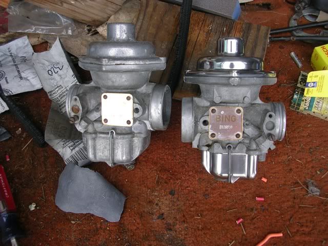
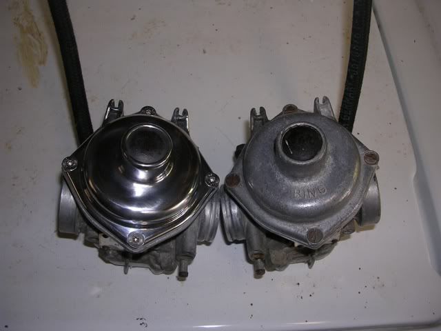
Yeah, just avoiding other work by fiddling about polishing the carbs. I've done one cap and one bowl, and I think I'll stop here and pick up the shine project the next time I have the carbs apart for actual work. The left one is, as yet, unpolished and I think I'll leave it that way--one can see only one carb at a time, no?

No-name carb top:

Image

A side view:

Image

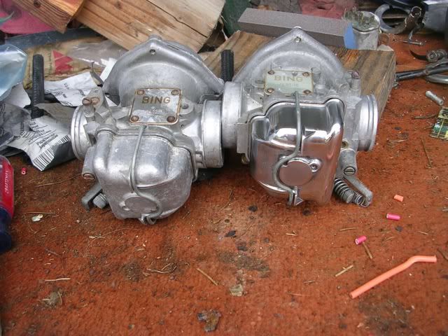
And the view we'll all see when the bike goes down:
Image

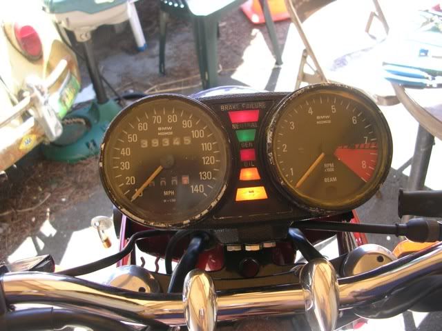
Tomorrow it's back to dicking about with electricity, hoping to make the dash lights function.
Call me Mel. Some years ago- never mind how long precisely- having little or no money in my purse, and nothing particular to interest me at home, I thought I would ride about a little and see the other parts of the world.
Chuey
Posts: 7632
Joined: Mon Aug 02, 2010 11:56 pm

Re: Woo Hoo! A Big Project!

Post by Chuey »

Hah! My bike is already running but not quite optimally yet, and with your electricity saavy you may be on the road before me. And......your carburetor tops way outshine mine. Lookin good.

Chuey
User avatar
melville
Posts: 1815
Joined: Tue Aug 03, 2010 8:32 am

Re: Woo Hoo! A Big Project!

Post by melville »

Yeah, I didn't dick about with electricity until today. Mrs. melville has had me clearing brush and crap and making dump runs mit the Kombi in preparation for framing a deck on the east side of the house. Finally, back to our MC drama.

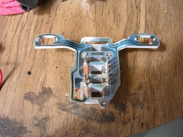
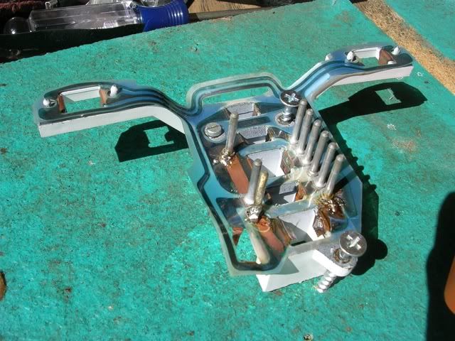
So the dash lights were not functioning. This thing was the difficulty:

Image

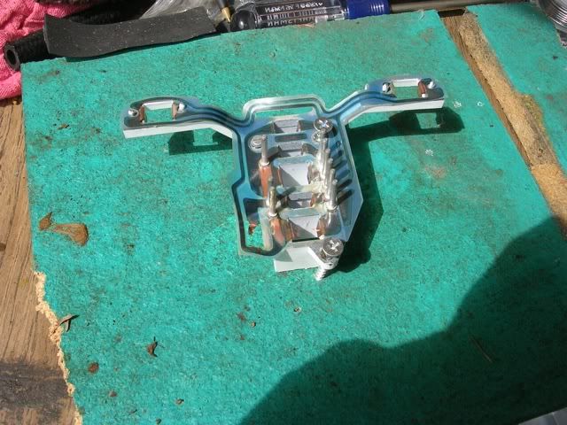
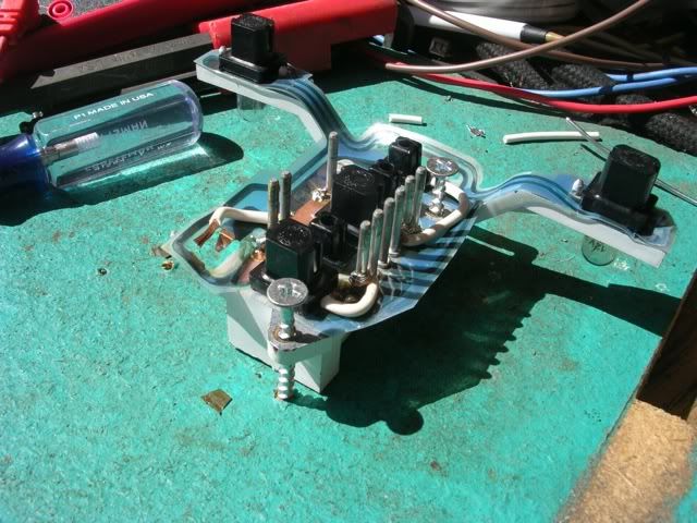
It holds the various lights in place in the instrument pod, running power from the pins through some copper foil to flexible tangs which engage the bulb holders. I pulled the bulb holders and cleaned the contacts, but it didn't help. I then checked continuity from the pins to the tangs and found a few that weren't on speaking terms. I was prepared to buy a new flexible circuit board, but figured I'd try a little fix first. e28rusty over to advrider mentioned gobbing on some solder to improve continuity, and I gave gobbing a go, first securing the unit to a board:

Image

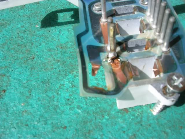
Then gobbing some of the pins that weren't connected:

Image

Image

This brought the hot back to the top four lights and the ground back to the high beam, turn signals, and instrument lights. I did not try to fix the ground side of the brake fluid level light, as it was in a tight space with a high probability of shorting out several other functions if I were to goof up.

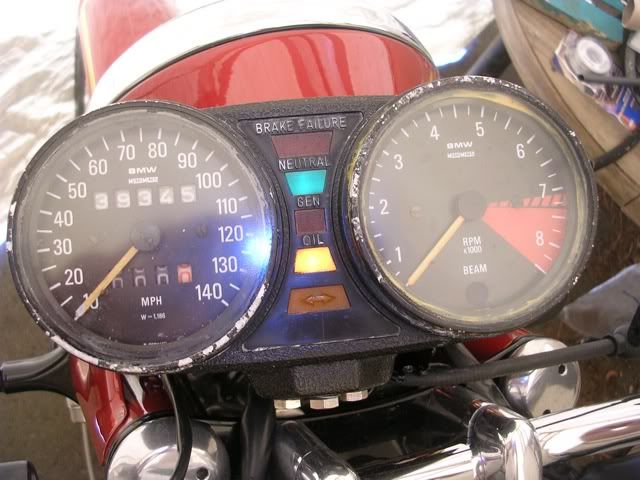
I put the pod back together, plugged it in, and turned the ignition on:

Image

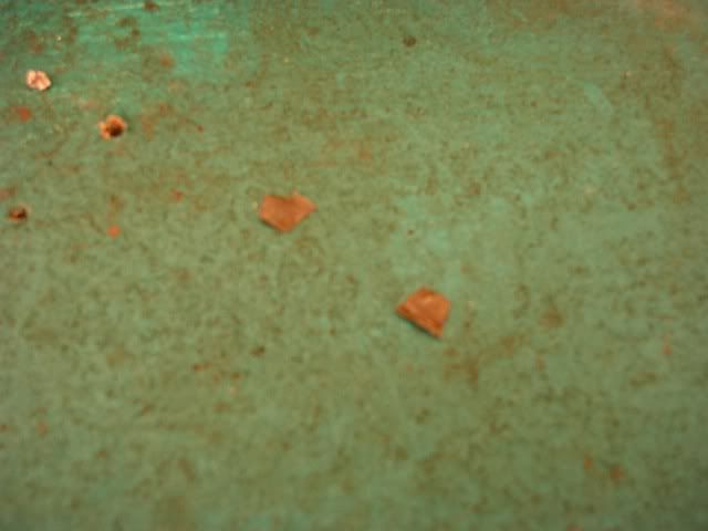
I've got the neutral light and the OP light working, but the gen light was dark. Like on an alternator equipped VW, that light is a necessary part of the charging system, so I took the pod off and apart and looked for the trouble, as I had good continuity and a working bulb when I tested the stuff off the bike. I pulled the bulb holder and found these inside the gen light space:

Image

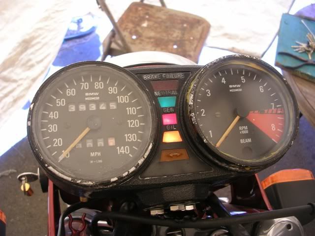
Those are bits of copper that fell off the tangs that meet the bulb holder, leaving them plastic and non-conducting. In a McGyver moment, I tried some wee bits of alu foil tucked in between the plastic and copper foil of the flexible circuit, and bent down to function as the copper tangs did before. And success!

Image

Pod now mounted up:

Image

I have the lights you see functioning, plus the instrument illumination. High beam indicator, turn signal indicator, and brake fluid level are not working, but I think I can live with that.
Call me Mel. Some years ago- never mind how long precisely- having little or no money in my purse, and nothing particular to interest me at home, I thought I would ride about a little and see the other parts of the world.
Chuey
Posts: 7632
Joined: Mon Aug 02, 2010 11:56 pm

Re: Woo Hoo! A Big Project!

Post by Chuey »

Mellville, is there a general scheme of how those pins work? What I'm asking is, is one side ground and one side power? Be gentle with me. I don't do this kind of thing often. People who work intuitively with electrical stuff often use words that don't make sense for me. It is not possible to offend my by making it simple.

For instance, the term "open circuit" means a short, I think, but I don't quite understand it. Some other terms are right at the edge of what I can comprehend at this point.

Thanks.

Chuey
User avatar
melville
Posts: 1815
Joined: Tue Aug 03, 2010 8:32 am

Re: Woo Hoo! A Big Project!

Post by melville »

Chuey wrote:Melville, is there a general scheme of how those pins work?
Funny you should ask! I have the info right below:
Chuey wrote:What I'm asking is, is one side ground and one side power? Be gentle with me. I don't do this kind of thing often. People who work intuitively with electrical stuff often use words that don't make sense for me. It is not possible to offend my by making it simple.

For instance, the term "open circuit" means a short, I think, but I don't quite understand it. Some other terms are right at the edge of what I can comprehend at this point.
Some of these have their operative switch closing to ground--brake fluid level, neutral, generator, and oil pressure. Those share a "hot" input. Others have their switch on the hot side--high beam, turn signal, and instrument lights. They share a ground.

It's not completely intuitive for me either. I try stuff, screw up, try something else, screw up, leave it for a couple days, think of another way while surfing/riding the bike/walking the dog, try that, and still be wrong. I'm actually taking a community college class this fall on automotive electrics in the hope of becoming less iterative in my electrical approach. It's mostly voodoo at this point.
melville, last October wrote:
mefrank11 wrote:
melville wrote:On to the next problem--does anyone out there have a reference for which pin does what on a 1975 /6? From the wiring diagram in my Haynes, some of these have the operative switch on the hot side and some on the ground side. I appear to have power at the plug but it may be getting lost in the instrument pod.

Image
I have a 1975 r75/6 If you tell what you want to know if you tell me how to test it . You may just need the flex circuit thats in there . I think thats all there is in there for electric Frank
Thanks. I ended up opening the instrument pod myself anyway, and using that and my Haynes wiring diagram I come up with:

1. Hot for turn signals
2. Ground for oil pressure light
3. Hot for instrument lights
4. Ground for charge light
5. Ground for brake fluid light
6. Ground for neutral switch
7. Ground for high beam, dash lights, turn signals
8. Hot for high beam indicator
10. No connection in the pod
12. Hot for brake fluid, neutral, charge, and oil pressure

I'm playing with the pod and a multimeter looking for continuity today but I'm also distracted by football and later by the Giants going for #2 against the Phillies. Over the next week I'll check for the appropriate signals at the plug.
Call me Mel. Some years ago- never mind how long precisely- having little or no money in my purse, and nothing particular to interest me at home, I thought I would ride about a little and see the other parts of the world.
chasbmw
Posts: 765
Joined: Fri Aug 06, 2010 7:40 am
Location: Bath UK

Re: Woo Hoo! A Big Project!

Post by chasbmw »

Someone on this board has a very good 74/75 wiring diagram, I'm on the road at the moment so can't say who , but if you look at my posts in march April you should find it.

The wires that go to the undertank master cylinder are important, one of them needs to be grounded, if not the indicators and the indicator warning light won't work. This had me going round in small cycles b4 I found out what the problem was.

( I had fitted a 13mm handlebar mastercylinder, and had simply taped off the 2 wires going to the undertank one)

Charles
Charles
Image
Replica 1070 R90/S (based on 82 RT)
1975 R90/6
Deleted User 287

Re: Woo Hoo! A Big Project!

Post by Deleted User 287 »

Chuey wrote:For instance, the term "open circuit" means a short, I think, but I don't quite understand it.
Chuey,

An "open circuit" is one that is normally continuous but is no longer continuous due to a break, either by a broken wire or connector or an open switch.

A "short circuit" is when two wires are connected that should not be. This can be caused by vibration wearing through insulation, but more likely by accidentally touching the positive terminal of the battery to the frame with a screwdriver or wrench (always disconnect the ground on the battery first), or by causing a short at the diode board with the front cover and not disconnecting the ground wire first.

Short circuits are marked by their dynamic properties: sparks & smoke.
Open circuits are usually very boring.
Major Softie
Posts: 8900
Joined: Tue Aug 03, 2010 1:46 pm

Re: Woo Hoo! A Big Project!

Post by Major Softie »

justoneoftheguys wrote:
Chuey wrote:For instance, the term "open circuit" means a short, I think, but I don't quite understand it.
Chuey,

An "open circuit" is one that is normally continuous but is no longer continuous due to a break, either by a broken wire or connector or an open switch.

A "short circuit" is when two wires are connected that should not be. This can be caused by vibration wearing through insulation, but more likely by accidentally touching the positive terminal of the battery to the frame with a screwdriver or wrench (always disconnect the ground on the battery first), or by causing a short at the diode board with the front cover and not disconnecting the ground wire first.

Short circuits are marked by their dynamic properties: sparks & smoke.
Open circuits are usually very boring.
Yes, a "short" circuit is one that is shorter than it is supposed to be: it being "shorter" in that the load is no longer included in the circuit. "Open" means a break or open switch, "closed" means a continuous circuit functioning as it should. SInce people often tend to think of a switch as like a gate or door for controlling the flow of electricity, it's a bit counter-intuitive that "open" and "closed" mean the exact opposite of what they would mean with a door.
MS - out
User avatar
melville
Posts: 1815
Joined: Tue Aug 03, 2010 8:32 am

Re: Woo Hoo! A Big Project!

Post by melville »

Well, it's been a coupla weeks since we checked in.
melville, a coupla weeks ago wrote:I have the lights you see functioning, plus the instrument illumination. High beam indicator, turn signal indicator, and brake fluid level are not working, but I think I can live with that.
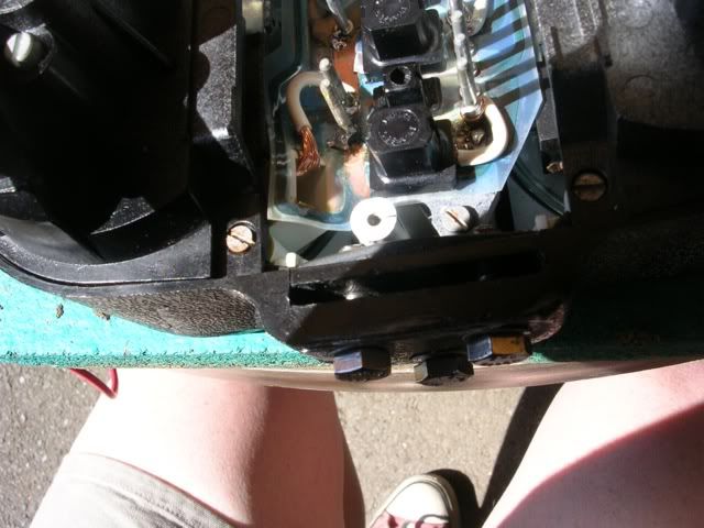
No, I can't live with that. I took the instrument pod off the bike, took it apart, and worked some hot molten metal magic, this time with wire.

I added wires to take the happy electrons to the ground side of the brake fluid light, and the hot side of the turn signal light and the high beam indicator. Looking like so:

Image

There is some empty space on those pins under their cover, plenty of room to wrap wire and solder it in place. Then I ran the wires to the bulb holes, stripped and flattened to meet up with the bulb holders. Assembled into the pod:

Image

And mounted up, with the brake fluid switch forced into contact:

Image

The instrument illumination is still functioning, and the high beam indicator doesn't show in the bright sun, but it works.

Further progress awaits the space aliens leaving a bag o' cash in the yard......
Call me Mel. Some years ago- never mind how long precisely- having little or no money in my purse, and nothing particular to interest me at home, I thought I would ride about a little and see the other parts of the world.
Deleted User 287

Re: Woo Hoo! A Big Project!

Post by Deleted User 287 »

Those are your "working on the bike" shoes, aren't they Mel? :)
Post Reply